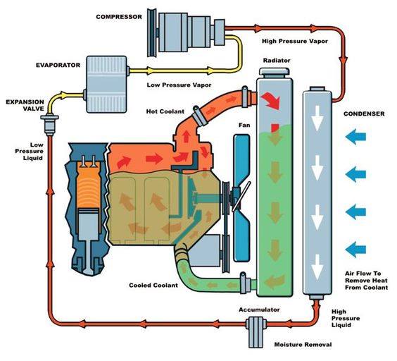
Cooling system Figure 1-24. engine cooling system flow diagram Coolant flow diagram powerstroke system ford air cooling through stroke power engine egr intake cylinder manifold 4l filter sensor cooler
Mercruiser 3.0 Cooling System Diagram
Cooling system heating vehicle systems
Sistem hose radiator pendingin mesin
Coolant diagram flow subaru cooling direction system post engine forester outback draining subarus forum legacy impreza sounds high vehicle 1990Cooling system block small engine big coolant flow basics works lt1 lt4 reverse where both How the cooling system works, basicsFlowchart of the cooling system calculation..
How does the coolant flow???Cooling flowchart calculation Cooling diagram engine system inboard water boat raw circulation typical gifHow to calculate the concentration of coolant in a car.
Vehicle service on heating and cooling systems to prevent failure
5.9 cummins coolant flow diagramDiagram cooling system flow 2003 thermal management component lager paths showing order click Mercruiser cooling system drain diagram mpi 3l alpha plugs mercury plug bravo point parts standard ec engine motor single hose2001 2.3l coolant hoses. part numbers?.
How engine cooling system works?Mercruiser 3.0 cooling system diagram Repair guides6.0 powerstroke coolant flow diagram.

Radiator cooling coolant automotive natrad quic depicts
Pfd diagramme edrawmax edrawsoft processingCooling system diagram flow engine repair dodge guide ford chevy ram 2005 autozone 1996 1997 schematic hose radiator fluid 1998 ('98-'00) coolant flow directionMercruiser 3.0 cooling system diagram.
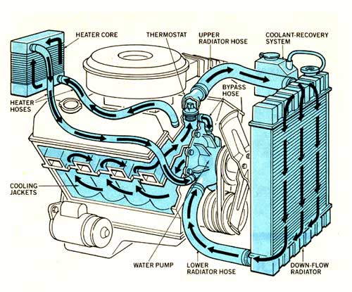
Cooling system diagram, showing flow paths and component order. clickDirection of coolant flow in an e30 m42 Engine cooling system car working coolant works mechanical water fan pressure types cars process engineering insideDiagram flow mercruiser cooling system closed engine water boat v8 loop marine perfprotech diagrams gxi technical 10th monday february overheat.

Mercruiser cooling system mpi drain parts diagram alpha mag 350 point standard single bravo 0l marine section engine mercury 1998
Generator 35c2 corps armyFlow diagrams Heater core vs radiatorCooling process flow diagram.
Figure a.14: fresh water cooling system diagramCooling system flow Thermostat: how it works, symptoms, problems, testingRadiator car turbo engineering e90 flush flushing coolant mechanic vixion conditioning charts rover fluid.
Coolant car water concentration diagram system cycle cooling radiator engine antifreeze process auto calculate through fluid cool understanding mixture do
Coolant ranger ford diagram 3l flow 2001 part hoses cooling system parts numbers forums soledad edited last mazda needWorking of engine cooling system Cooling system flow chart westfalia vanagon 1986 pipe crossover when opens goDiagram coolant flow cummins hose jeep crd engine cooler line core drawing note tubes pipes connection egr.
Cooling system thermostat diagram works car parts 2009 dodge journey radiator problems work automobile symptoms engine water cars automotive control .


